9 minutes
Fsae Fuse Box
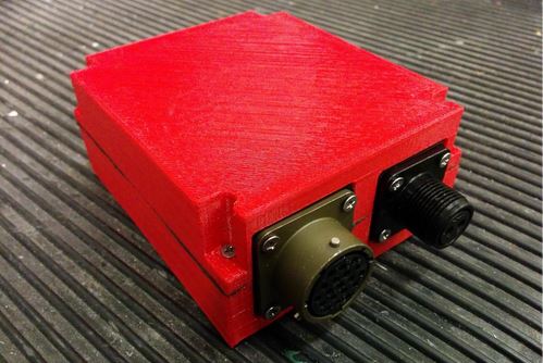
This was one of my final projects while on the University of Calgary FSAE teams as Electrical Team Lead.
DESIGN
Objective
The objective is to develop a module which will provide a centralized distribution of power to the Formula SAE car’s various electrical systems in accordance with the rules set by the SAE for the FSAE competition.
Background
Previous years the electrical wiring was just relays and inline fuses which then migrated slowly to being mounted on a crude centralized board. Beginning in the 2012-2013 season a centralized fuse box was used instead of the board. The box held all the relays and fuses and contained internal wiring. This allowed the team to quickly replace the entire system if needed via a mill-spec connector and greatly reduced the bird’s nest of wiring. The system was significantly more professional and elegant than previous methods. Draw backs included internal wiring which sometimes wiggled loose and caused issues; removing and replacing fuses and relays was not as easy as originally intended and the internal wiring was complex and understanding the system was more difficult than it should be and only two people really understood it.
Design Points
For the design of the new fuse box the following design criteria were used:
Simplicity
A goal of the new design was to reduce the complexity of the final product and make it more intuitive for users to debug and learn the working of. Increasing the simplicity will also help improve the ease of diagnosing a problem.
Reliability
Reliability was an important design point due to electrical issues in past years. When a PDM was used the reliability of the system was generally very good so the goal was to maintain that level of reliability with the new design.
Weight reduction
The first and most important design goals were simplicity and reliability. The goal was to increase simplicity and reliability without any weight gain; any loss in weight would be considered an extra benefit but was not a large focus during the design phase.
Cost
Cost was not an important factor but was a constraint in that the design and manufacture needed to remain within the team’s means.
Operation Conditions
Circuits
The fuse box will control the power for all of the following circuits:
- Fan
- Fuel Pump
- Ignition coils
- Injectors
- Kill switches
- Start solenoid
- ECU
- Oxygen (02) sensor The power for the start motor is not routed through the fuse box because of the extremely high current.
The following table shows the expected current for each circuit on the car. The amperages were determine from manufacture specifications or testing.
Table 1: Expect circuit amperage
| Circuit | Expected Maximum Amperage |
|---|---|
| ECU | 1-16 amps (engine load dependent) |
| Fuel Pump | 15 amps |
| Fan | 20 amps |
| Injection and Ignition | 15 amps |
| Oxygen sensor | 5 amps |
| Main Relay Fuse | 3 amps |
FSAE Rules
The only rule that affects the design of the PDM is the following:
IC4.3.1
C. Must be a push/pull Emergency switch with a minimum diameter of 24mm. The switch must be installed such that:
- From the ON position, pushing on the switch will disable power to the ignition and all fuel pumps, and
- From the OFF position, pulling on the switch will enable power to the ignition and fuel pump(s). Switches that require a twist or twist and pull to enable power are acceptable.
When the dash kill switch is actuated, the PDM must disable power to the ignition circuits and all fuel pumps. Every other circuit can still have power when the dash kill has been actuated.
Fuses
ATM Mini fuses were chosen for the design. Smaller and therefore lighter but still relatively common replacement parts, and are equally as reliable as the larger ATC/ATO fuses. To incorporate the fuses into a PCB design through-hole fuse holders were used.
Relays
Panasonic CN-M through-hole relays were chosen for the circuit. These relays are rated to 30 amps and are used in many automotive applications. These were the smallest relays that were found that could handle the expected amperages of every circuit. More information can be found in the spec sheets in the Appendices.
Voltage Regulator
A voltage regulator was added to provide 5 volt power out puts for the driver dash display and an extra output for expansion. This way no inline regulator need to be solder in and it further centralized the power distribution allowing for faster diagnostics.
Connectors
The design incorporates two connectors, the reason is to separate the power input and ground from the outputs and signals. Main reason for this is because of the higher current for the input power. Mill-spec connectors were used because of their excellent durability and current capacity
Circuit
The circuit is the same as previous years using four relays to distribute the power through 6 fuses. The
circuit and board layout were made in EAGLE CAD.
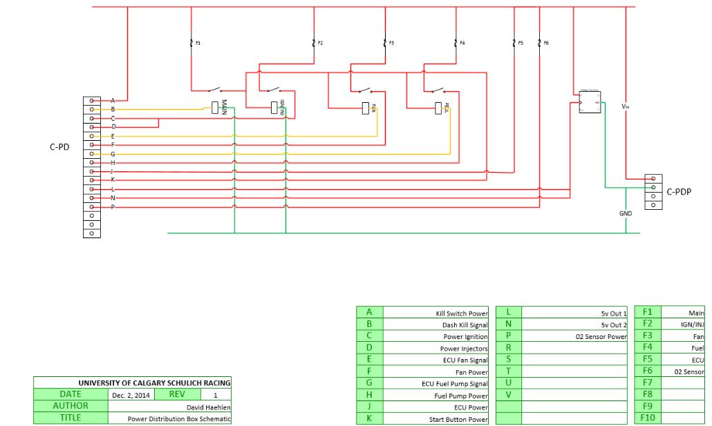 The actual circuit was made this way however the only deviations include a different pin out and pin K was
not used, instead the start button gets its power directly from the kill switch behind the dash; this saved
running a wire from the back to the front of the car and the circuit behaves the same way.
The actual circuit was made this way however the only deviations include a different pin out and pin K was
not used, instead the start button gets its power directly from the kill switch behind the dash; this saved
running a wire from the back to the front of the car and the circuit behaves the same way.
Pin out
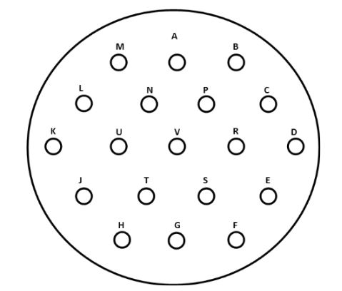
Table 2: Mill-Spec Pin Out Table
| Pin | Purpose | Color |
|---|---|---|
| A | + 5v | Red |
| B | Empty | - |
| C | Kill Switch Power | Black |
| D | Start Button Power (not used) | - |
| E | ECU Power | Black |
| F | Empty | - |
| G | Empty | - |
| H | Ignition power | Orange |
| J | Injector Power | Orange |
| K | Fan signal from ECU | Orange/Purple |
| L | Empty | - |
| M | + 5v (un-used) | - |
| N | Empty | - |
| P | Empty | - |
| R | Signal from Dash Kill | Yellow |
| S | 02 Sensor Power | Yellow/Black |
| T | Fuel Pump Power | Orange |
| U | Fan Power | Orange |
| V | Fuel Pump Signal From ECU | Orange/Brown |
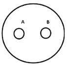
Table 3: Power Pin Out Table
| Pin | Purpose | Color |
|---|---|---|
| A | PCB Power | Red |
| B | PCB Ground | Green |
Circuit Boards
It was decided to use a circuit board for the fuse box in order to fulfill the goals of simplicity and reliability.
In order for the circuit board to handle the large currents a board with a thick copper coating was needed. Using trace width calculators it was determined that for a single sided circuit a copper board with at least 4 oz. was needed.
Table 4: Current, trace width and copper thickness
| 1 oz. copper | 2 oz. copper | 4 oz. copper | |
|---|---|---|---|
| 1 amps | 0.3 mm | 0.15 mm | 0.0751 mm |
| 5 amps | 2.77 mm | 1.38 mm | 0.691 mm |
| 10 amps | 7.19 mm | 3.6 mm | 1.80 mm |
| 15 amps | 12.6 mm | 6.29 mm | 3.15 mm |
| 20 amps | 18.7 mm | 9.36 mm | 4.68 mm |
| 25 amps | 25.5 mm | 12.7 mm | 6.37 mm |
| 30 amps | 32.7 mm | 16.4 mm | 8.19 mm |
The table gives trace width for a temperature rise of 10 degrees Celsius, an ambient temperature 25 degrees Celsius and a trace length of two inches.
The trace width is calculated as follows: First, the Area is calculated: Area[mils^2] = (Current[Amps]/(k*(Temp_Rise[deg. C])^b))^(1/c) Then, the Width is calculated: Width[mils] = Area[mils^2]/(Thickness[oz]*1.378[mils/oz]) For IPC-2221 internal layers: k = 0.024, b = 0.44, c = 0.725 For IPC-2221 external layers: k = 0.048, b = 0.44, c = 0.725 where k, b, and c are constants resulting from curve fitting to the IPC-2221 curves
Reference http://circuitcalculator.com/wordpress/2006/01/31/pcb-trace-width-calculator/
It should be noted that traces over .4 inches (10.16 mm) in width and copper over 3 oz. are not included in the IPC-2221 curves and the results are extrapolated.
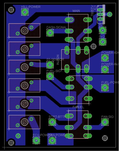 Figure 4: Layout generated in EAGLE CAD
The schematic provided from the relay manufacture was a bottom up view while the fuse holder schematic was given in a top down view. It was decided to mirror the fuse holder schematic since this was easier and this is why the manufacture schematic and the CAD schematic do not match.
The larger traces were made with the polygon tool because they were larger than the largest trace available in EAGLE CAD. The traces that were carrying lots of current were made as large as possible to be able to handle the current.
Conclusion
With the better documentation and the more intuitive, organized manner of the PCB the new power distribution module has reduced the complexity of itself and the electrical system and by way of this also made trouble shooting issues easier. The reliability of the previous fuse box was already up to a good standard and it can be said that the new design meets the same expectations for reliability.
A goal was to be lighter or of equal weight to the old model and weighting the two systems shows about a 100 g weight reduction the previous design 270 g with the new design at 167 g.
PCB MANUFACTURE
The circuit board was etched in house using a positively sensitized 4 oz. copper board.
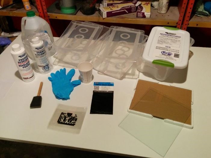
Materials
- Ferric chloride copper etchant
- Sodium Hydroxide positive developer
- Distilled water
- 3-4 Bins -1 for each developer, etchant and water rinse -Additional bin may be used to surround etchant with warm water to speed etching -Brush -Gloves -Mix cup -Exposure glass -Circuit print outs
Steps
- In a dark room remove copper from bag
- Place circuit print outs (three were used to ensure good opacity) on copper
- Place glass over top
- Expose to a UV source (florescent light) for around 8 minutes (time depends on light source)
- In a dark room again place PCB into developer
- Wait a about 2 minutes and the circuit should become visible
- Rinse in water to end development
- Place in etchant and agitate, can take a long time with 4 oz. copper
- Rinse in water
- Drill holes and solder components
Printouts were made with a laser printer cut out and staked together to increase the opacity to ensure a better exposure. When handling the copper in the chemicals be sure to wear latex gloves and avoid splashing the ferric chloride which will stain almost anything.
OPERATION
The following sections will help with the operation of the board and should aid in any troubleshooting should the need arise.
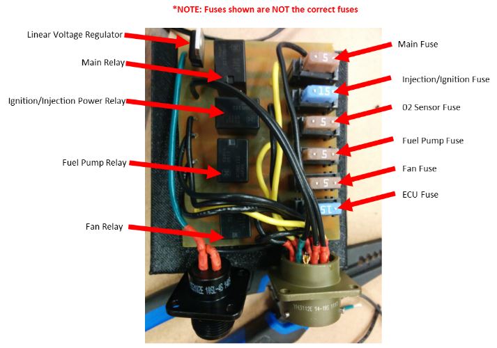 Figure 6: PCB Component layout
Table 5: Fuse Table
| FUSE | VALUE |
|---|---|
| Main Fuse | 3 amps |
| Injection/Ignition Fuse | 15 amps |
| 02 Sensor Fuse | 5 amps |
| Fuel Pump Fuse | 15 amps |
| Fan Fuse | 20 amps |
| ECU Fuse | 5 amps |
Figure 7: Trace Description
1705 Words
2015-01-24 22:17